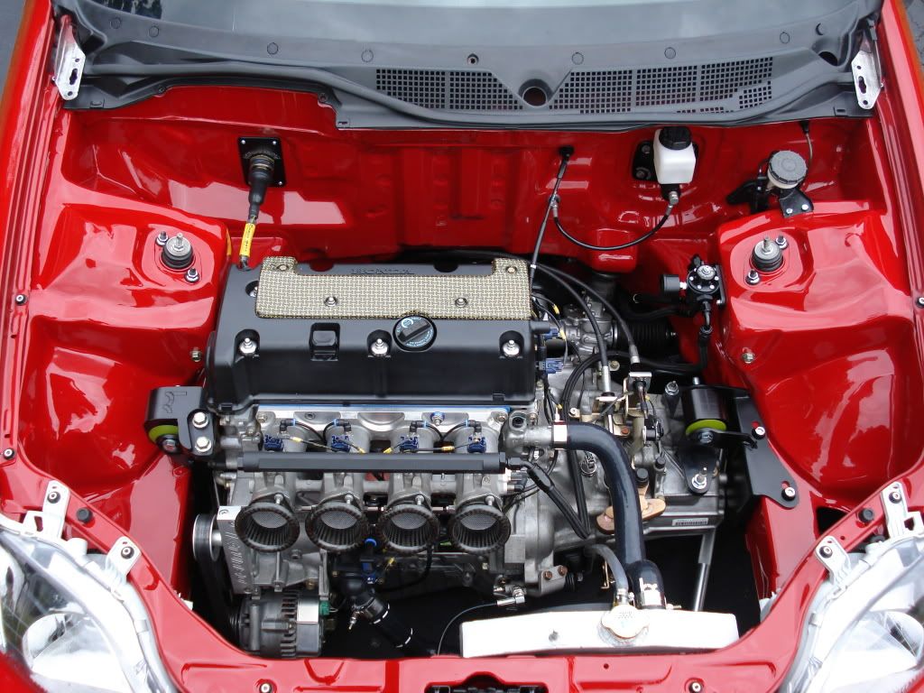
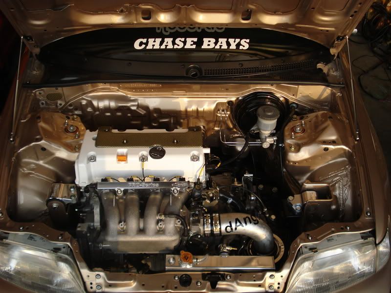
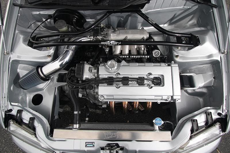
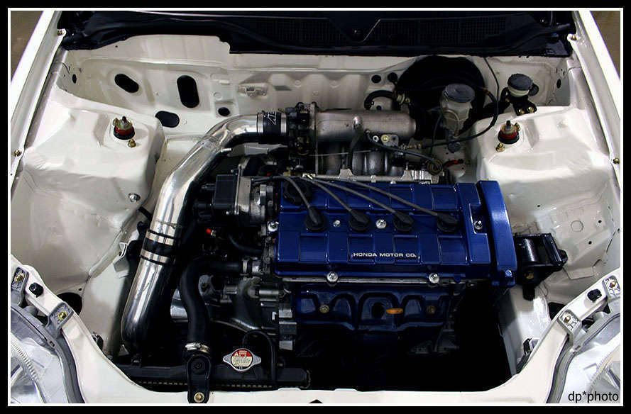
this is more or less a port from h-t that im tossing together for thejdm so we can all enjoy.
READ BEFORE ASKING QUESTIONS. IT MAY HAVE BEEN ANSWERED BELOW ALREADY!!!
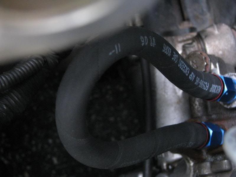
brake lines, fuel lines, clutch line conversions
- converting your fuel line/hydro clutch line to braided w/ fittings
hayce wrote: Is there any write ups out there (like the very helpful fuel line threads
) for converting the hydro clutch line to braided w/ fittings?
BoostedJeff wrote: its easy...
(2) -3 to 10mm adapter
-3 line
me and dan did ours with a 3ft line and a 2ft -3 line, with a -3 union in between
SPOON_BeIgHtEeNsEe wrote: or PM Flamenco-T he sells the line and fittings for 75 shipped .... line is 72" long
Also, a VERY resourceful thread for this for those who like pictures: http://honda-tech.com/zerothread?id=1545386
nerdsports wrote: WRITE UP: How to convert your fuel lines and ugly filter to Stainless -6AN hoses
or this one?
HOW-TO: convert the OEM fuel feed hard line to braided flex line for AN fittings
complete AN fuel line setup .pdf
http://www.edelbrock.com/automotive_new ... 641563.pdf
phresh_5 wrote: Fuel system wire harness installed:
[img]http://img206.imageshack.us/img206/5682/dsc00980gd8.jpg[/img]
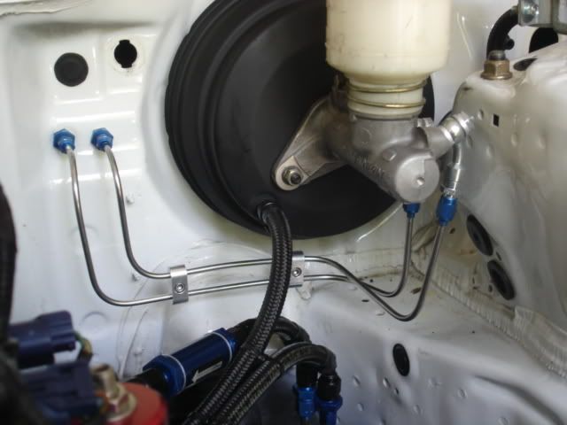
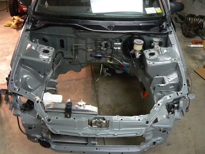
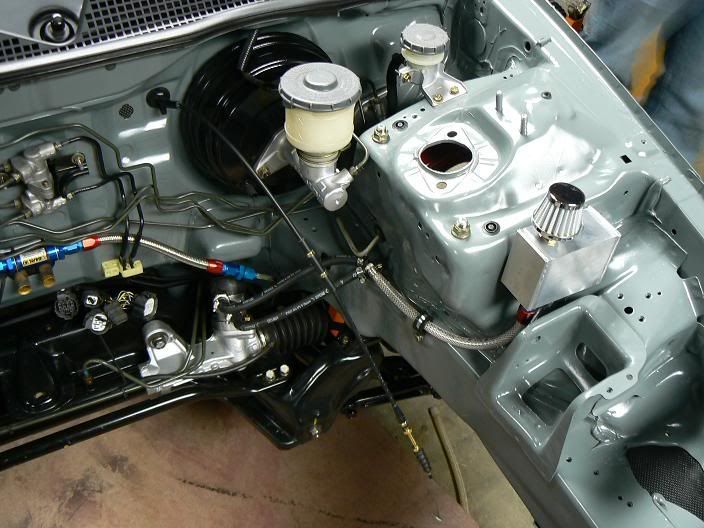
Brake lines behind firewall (completed). Rear lines are SS untill they go behind the subframe, then they go back to hard lines all the way back. All other lines are SS.
[img]http://img515.imageshack.us/img515/3395/dsc00974kl6.jpg[/img]
[img]http://img511.imageshack.us/img511/1786/dsc00975eg6.jpg[/img]
JDMorgan wrote: all brake/clutch lines are 3/16" line with m10x1.0 fittings, if you want to run an fittings run -3 tube sleeves/nuts. the only brake line not m10x1.0 is the front fitting on an abs master cylinder is actually m12x1.5. it still uses 3/16" line tho.
-NA-aLL-thE-wAy- wrote: I planned on using stainless hardline, but I didn't want to spend a ton of money on the flare tool. Then I decided I didn't like the look of the rear hardlines being inside the car (since the int is stripped) so I decided after I get it dipped I'll redo them with braided.
I have also heard about leakage problems. That's usually caused by the flare being done wrong: either the wrong degree of flare, or the end of the flare cracking do to overflaredness.
I said overflaredness.
SHG_EasyE wrote: some updated pics of mine....
[img]http://i159.photobucket.com/albums/t131 ... 030128.jpg[/img]
[img]http://i159.photobucket.com/albums/t131 ... 030123.jpg[/img]
since so many ppl have asked already this is the list of parts i used off summit racing.
(substitute one -6an hose end for a 45 deg one)
EAR-230206ERL Fuel Filter, Inline Mount, Blue, 85 Microns, -6 AN Male Inlet/Outlet, 1
EAR-581805ERL Fitting, Tube Nut, -5 AN, Aluminum, Blue, Pair, 1
EAR-581905ERL Fitting, Adapter, Tube Sleeve -5 AN, Aluminum, Blue, Pair, 1
EAR-991907ERL Fitting, Union Reducer, Male -6 AN to Male -5 AN, Male, Aluminum, Blue, 1
EAR-991945ERL Fitting, Carburetor Inlet, -6 AN Male to 12mm x 1.25 Male, Aluminum, Blue, 1
SUM-220690 Fitting, Hose End, Straight, -6 AN Hose to Female -6 AN, Aluminum, Red/Blue Anodized, 4
SUM-G1001 Hose, Braided Stainless Steel, -6 AN, 18 in. Length, 2
whole setup cost a little under 100 bucks including the new filter
g2_teg_ wrote: where in the world can i get those banjo bolts from? the ones i got from summit were too long.
- tucking your brake lines
RotiEatter wrote: I want to relocate the brake lines, but I'm scared of messing with them... haha.
Anyone have good pictures of how they relocated their brake lines and what kinds of lines they used? Thanks.
EF8kid wrote: Go look at the page before this for pics of mine. They sell all differents lengths of line @ your auto parts store and theyre like 5 bucks a peice. 3/16th size line for japanese/metric/import etc...I bent them with my hands!
kidkombo wrote: dood the hardlines will kink when you re route them....they are already bent in intricate ways, there is no way in hell you can do a clean tuck behind the firewall...so yes i think its a stupid question as well lol all you need is a tubing bender, tube nuts and sleeves and a ton of reverse flare -3 fittings to -3male...and you will be set for life!
stillrockin18s wrote: Where can I pick up some metal brake lines and fittings online so I can tuck my portioning valve and brake lines. I prefer just straight pieces, my boy has a good bender and flaring tool.
Also can the portioning valve be mounted on its side? I am thinking of tucking them under the wiper cowl.
painting, applying filler, weldinghondaZvic wrote: the metal lines and fittings can be picked up at your local autozone or whatever autoparts store you have, the lines come in rolls, and you can buy it by the foot or however much you need. at least here anyway.
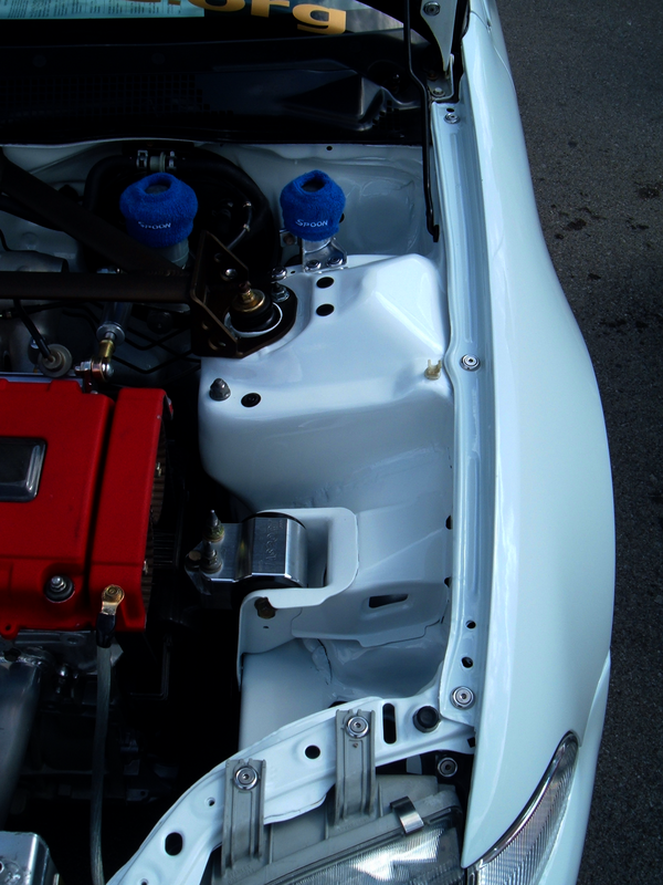
- shaving/painting your engine bay
JDMorgan wrote: usc icing is an example of a filler you can use. all polyester fillers are pretty much the same, it comes down to what they sell at your local auto parts store. i use evercoat products.
fventura03 wrote: do you (or anyone else) recommend using this on the shock towers and to cover small bolt holes in the engine bay? i'm trying to make my engine bay as clean as possible, but i dont want it to start cracking in a couple of years...
nerdsports wrote: you need to weld the holes shut first. then grind the weld down.
the icing is just a thin layer over the metal surface to cover the imperfections and leave a smooth flowing finish.
EF8kid wrote: bondo sucks, i used Evercoat Metal Glaze.
I_HATE_JDM wrote: evercoat rage extreme filler is your friend.
JDMorgan wrote: i never use normal fillers anymore. if i absolutely have to use a bunch of filler i use evercoat duraglass, but i like the polyester filler by evercoat. its expensive but it works awsome. it's very thin so you can feather it out quickly. i hate bondo brand products.... wont use them. evercoat has a sweet line of products so they have pretty much something for everyone.
JDMFantasy2k wrote: Any of you guys that have painted your bays, have you heard/seen/used this stuff??
https://www.paintscratch.com/
Apparently they sell OE paint in aerosol cans. Appears to have amazing feedback about the products and it's like 25/can.
Seems like a neat alternative for those guys who don't wanna krylon it and don't have a hvlp gun. I'm pretty interested in it i must say.
DarkBB4 wrote: usc icing
I think that is what (Bryan)Pandahatch used.......Ive heard good things about it too.
http://www.evercoat.com/productDetail.aspx?pID=1
[img]http://www.evercoat.com/imgs/products/MetalGlaze.jpg[/img]
-NA-aLL-thE-wAy- wrote: The Paint/Body special issue of Hot Rod Magazine said as long as it's 1/4 of an inch or less, and the chemicals are mixed correctly, you won't have an issue with cracking. Naturally you want it much thinner than 1/4".
Pandahatch wrote: I do a LOT of metal work, grinding, smoothing, etc...you don't necessarily have to seam weld. If I have a seam I grind it down almost flush to the panel under it and apply a couple spot welds to minimize distortion and warpage and grind those down, I apply filllr and end up taking off over half of what I apply. It's a long tedious project as well.
ezza wrote: I was told that when removing the seam sealant stuff you have to weld the seems for strength what exactly does seam welding do, and when you say a couple of spot welds, like 1 per 3 inches?
EF8kid wrote: I did ALL sanding by hand on my Cr-x's bay and the EK bay, cept on the core support like Brian...
oh evercoat metal glaze is kewl.
JDMorgan wrote: hand sanding with a block is about the best finish you will get, 2nd to an inline sander. rotating sanders tend to make shit wavy if you arent careful. most of the bay you cant even use an inline sander on tho so you have to pick between smaller blocks or rotating sanders.
evercoat and usc both have great products, just be sure to use the right product for your application and use it properly.
DarkBB4 wrote: wats a good THICK primer to spray to help fill scratches, i.e. make it easier to see flaws. etc.?
4d_ek9 wrote: I dont know if you can get in the US but in the uk i tend to use a brand called U POL and its called reface it awesome stuff you can whallop it on as thick as you wish and it will sag into the imperfections, you can get away with covering 40ish grit marks with it, and when its dry just guide coat and wet flat it with 500 / 800 depending on how thick u applied it.
Slappy wrote: My painter used a greenish filler primer(U-POL) that is thicker than your average primer. Once that first coat was layed on, any imperfections were more visible and could be touched up. Then a second coat was applied.
[img]http://autobodystore.net/Merchant2/grap ... polkit.jpg[/img]
-NA-aLL-thE-wAy- wrote: So is it best to use the metal glaze directly on the metal, then sand, then primer, or prime the bare metal, then glaze, then primer again? I know the metal glaze is designed to be used directly on bare metal, but I wasn't sure if one way was better than another. You know, chemical vs. mechanical bond and whatnot.
- seam sealer/stitch welding/weldingI_HATE_JDM wrote: I use evercoat rage extreme and it works very well.
PatrickGSR94 wrote: So what are you doing if you remove the seam sealer? I'm sure it has a reason for being there, are you sure it's a good idea to remove it?
JDMFantasy2k wrote:hey how are you guys getting rid of that seam sealer shit that is everywhere?
-NA-aLL-thE-wAy- wrote: Most people weld that seam; one for rigidity, two for aesthetics.
h22apwrdcivic wrote: sand blast
hondaboy4life wrote: or heat it up with a propane torch then wire wheel in places where you can reach.
-NA-aLL-thE-wAy- wrote: A torch and a wire wheel is actually faster/easier than sand blasting. I've done both. Sandblasting works, but it's time consuming, and time consuming means a lot of sand, and a lot of sand means more money. You can buy a wire wheel (for pneumatic tools, would be best) and a propane torch for under $20. The sheet metal is so thin on our cars I'm reluctant to sand blast in the same area for an extended period of time (like for the thicker seam sealer). Get a little heat in the sealer then hit it with a wire wheel, it'll come right out.
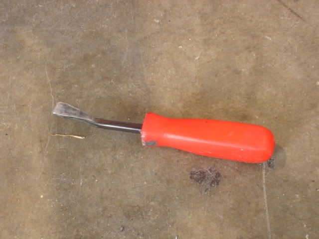
EF8kid wrote: I scraped every inch of seam sealer in my entire car mostly with this tool. Small prybar(also works great for separating spot welds):
[img]http://i161.photobucket.com/albums/t230 ... crx008.jpg[/img]
Some places i used a wire wheel too
JKGONZALEZ3 wrote: well i should ask i just took some seam sealer off and did some welding on the strut tower but i was wondering if you grind your weld down wont it weaken it or should it still be stronger than oem seam sealer was?
donut. wrote: welding makes the metal weaker in certain areas exept the particular area you weld. make sure you have the right setting
Boosted Rex wrote: The stuff your looking for is called self-leveling seam sealer. You use this stuff exactly like regular seam sealer BUT the key thing is that it is sandable because it is catalized. It costs about 30 bucks and comes in 2 tubes.
I can't remember the brand I used, but it was very similar to this
http://www.azautobodysupply.com/123fufamacas.html
Hayce wrote: You or anyone else mind elaborating on this?
Im up to here in my build now and Im unsure how to tackle it. Like is welding the seams the only options can you take it back flat and smooth it or? any ideas are good
EF8kid wrote: The tack's is stitch welding, He did multiple tacks on the one seam as u can see so he could make it all metal work and minimal filler.
[img]http://img.photobucket.com/albums/v739/ ... dimage.jpg[/img]
-NA-aLL-thE-wAy- wrote: The seam sealer is there to prevent water and moisture from getting in there and causing rust. If you stitch weld the seams (1-3" apart), around the strut towers for example, it adds strength to the chassis, as all the panels are tied together. Some choose to weld the entire seam continuously and then grind it down, but Panda is saying that isn't necessary.
hondaboy4life wrote: with sheet metal u just have to do a series of tack welds. Do one at one side, then another furthest away from the one u just did, then go back and do one 1 inch from the 1st one, etc etc. JUst dont let it get too hot.
sic944t wrote: i dont know if this will work its a trick my dad talked about from torch welding but you could get a wet wool sock and put it on the back side as a heat sink to prevent some of the warping
civicandy wrote: But from what i'm told, it's because it's in the middle of a large area, with no support to keep it from warping. Unlike when you do an antenna, which has curved metal around it to keep it from warping.
wiring/electricalturbob18si wrote: water promotes rust, use a piece of copper on the backside of where your welding. Copper is a excellent heat sink and will pull the heat away from where your welding. There is a copper tool for this with a handle. check http://www.eastwoodco.com, they have alot of things that help out on our projects
- main engine harness tuck
drevinder wrote: engine baY'S LOOK good..but one question where do u guy's put the driver side harness ...and the passenger side ....make hole somewhere ? if so where..i'm stumped
ECKOTYPER wrote: what u wanna do is connect the passanger and driver side on the interior side of the firewall, and get all ur connections to come out of a central hole ... i cut a hole about as big as the driver side hole, underneath the heater core, and ran my harness in through that, ( i retained my heater core) so the heatercore hoses kinda disguise the harness below
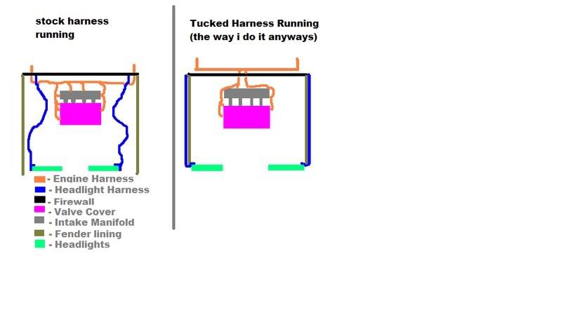
ECKOTYPER wrote:some people ahve been asking me how to do some tucks and stuff, so i made a simple diagram showing more or less hwo a stock engine is routed, and how a tucked one is routed (when i do it) im not getting into detail because if u read this thread instead of looking for pictures theres alot of helpful material in here... heres 1 visual... so please stop asking for help (j.k im glad to help)
[img]http://img.photobucket.com/albums/v627/ ... aasdfa.jpg[/img]
SkankyEJ7 wrote: the only thing that MAY (its been talked about but never really proven) affect your engines performance would be altering the length of the wires would be the injectors. so i left the injector wiring the stock length on my harness, but everything else its custom length. and my car runs fine.
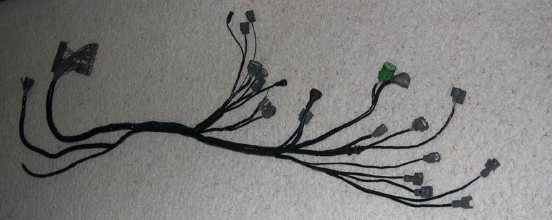
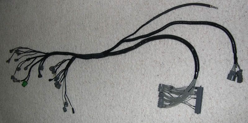
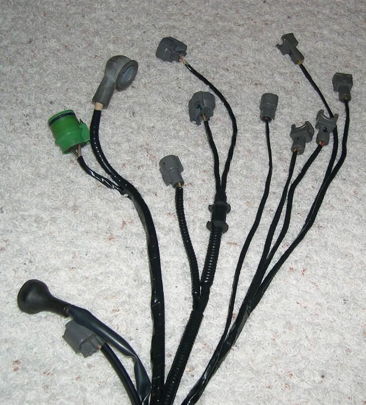
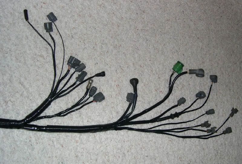
Rywire wrote: What are we looking at?? This is a harness for a bseries obd1 car (ill make them for obd0/2 also)
Its basically like a EK harness witout the drivers side shocktower plug. One end is all the engine functions ready for a Bseries with chipped obd1 ecu (to turn off things like vtec oil pressure, eld, and o2 heater).
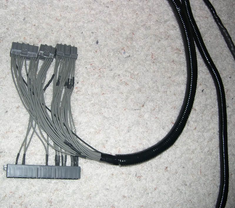
The other end has the ecu /jumper intergrated. It also has the fuse box power wire setup to be used under the dash as well as the drivers side 14pin connector and 2 pin connector ready to be plugged in under the dash out of sight...
Feeding it through the firewall can be done easily once the stock harness is removed and pulled inside.
This is my first attempt at a tuck harness, and im sure it will improve as I learn more tricks... The only change I can think to make on this is to cover the long loom areas with that shiny plastic covering over split wire loom.
Give me feedback on this please, thanks everyone! Oh, and these are not going to be cheap.
-Ryan
[img]http://i70.photobucket.com/albums/i85/d ... uck001.jpg[/img]
[img]http://i70.photobucket.com/albums/i85/d ... uck006.jpg[/img]
[img]http://i70.photobucket.com/albums/i85/d ... uck005.jpg[/img]
[img]http://i70.photobucket.com/albums/i85/d ... uck004.jpg[/img]
[img]http://i70.photobucket.com/albums/i85/d ... uck002.jpg[/img]
Civichatch2k wrote: What gauge of wire to you need if you are extending the harness?
JDMorgan wrote: no thicker than it is now, but some of the wires are shielded. why would you ever want to add more wires to a car? most of us are ripping out every wire possible and shortening ones that are required.
Civichatch2k wrote: Let me rephrase. I may have to extend the headlight harness and the horn. I was just wanting to match the gauge of wire if that has to occur. Other than that I am not doing anything other than tucking the wires.
- tucking your headlight harnessJDMorgan wrote: i think most of the wiring is around 18awg. not 100% sure tho. i actually have a box of wire from crap i took out of my harness, when i need wire i look for the same color and size and its normally there.
Civichatch2k wrote: on the Ek's how are you guys hiding the headlight harnesses.
I know you are running them through the fenders but because they run in the front of the car and then to two main plugs after you get the harness off, what are you doing to re-route them?
I have the harness on the passenger side which is connected to the fuse box and I have the driverside which runs to the fire wall.
gabebauman wrote:[img]http://img76.imageshack.us/img76/5484/m ... webzv9.jpg[/img]
JDMFantasy2k wrote: on mine, i routed the headlight harness through the drivers side only. All of the wires in the passenger side of the harness are for AC components aside from the wires for the horn and cooling fan. So i ran those wires through the interior, re-pinned them into the connectors on the drivers side, and then ran wires through the harness for them.
American.Graffiti wrote: Question:
After stripping my harness I see that some wires have interference (sp?) insulation, my question is how do you advoid cutting the wires to length for the tuck? (Hope my question is clear).
B18EG6 wrote: you are referring to RF shield for some of the signals (distributor, knock are two that come to mind quickly).
If you choose to cut these, the best option is to replace the whole length from pin to pin with an already shielded wire. Some have had success with cutting the whole wire, soldering the conductors together, and resoldering the RF braid over top of them... however this is not perfect.
NJcoupe wrote: Where did u purchase the stuff to re-loom your harness. and what sizes?
B18EG6 wrote: bought the smaller expandable sleeving from waytek wire, and the larger sleeving locally. The sleeving ranged from 3/16" - 1/2" when collapsed. I also got a few rolls of wire from waytek for some good price Towards the end of assembly, I didnt plan too well and thats why there is electrical tape
The connectors were bought from Allied, along with their crimpers. The two posts on the firewall are for the starter and alternator leads, both 4ga.'
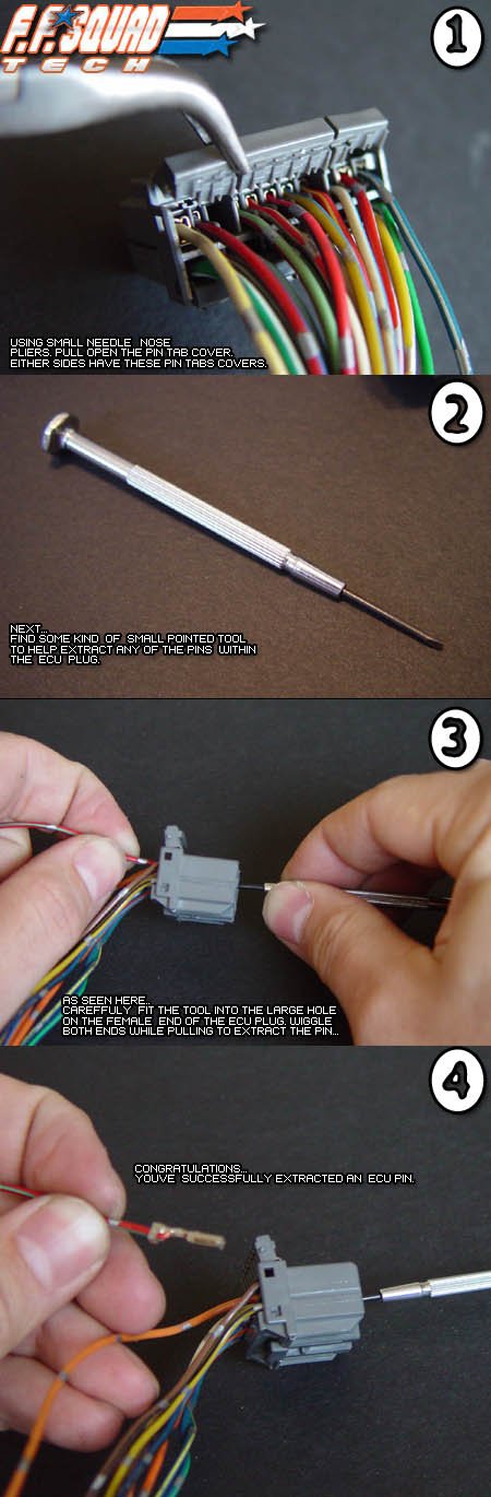
.adam. wrote: can someone give me some advice on depinning the connectors on the engine harness....i am tryin to put the braided sleeving on and cant get the connectors off. i know to take out the white inner piece, but then i get stuck. anyone got some pics or advice.
Hayce wrote: Tiny screwdriver or use a de-pinner...
What sleeving are you using? Stuff I used had velco and wrapped around the loom.
.adam. wrote: i was planning on ordering this:
http://www.xoxide.com/techflex.html
blackb18c1eg wrote: try Snap On, I just ordered a universal de-pinning tool from them. I think it lists for like $45, sorry I dont have a pic or a link.
.adam. wrote: o yeah and for the injectors i have yellow, white, red, and brown.....can anyone verify which colors go with which cylinder?
teal_dx wrote: I'm guessing you have white instead of blue...
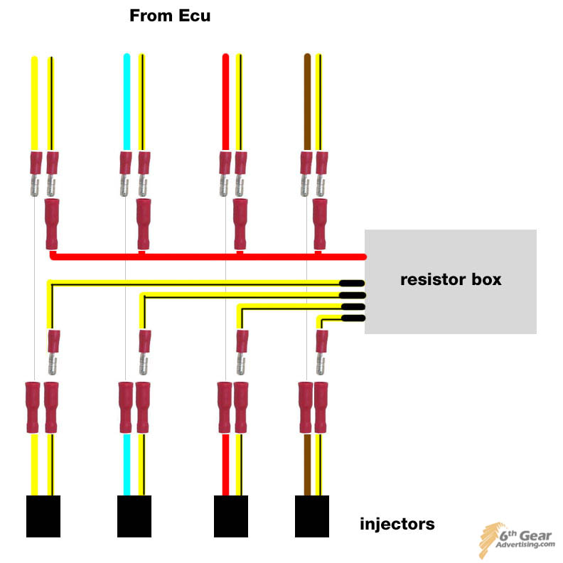
[img]http://www.6thgearadvertising.com/misc2 ... or_box.jpg[/img]
ignore the resistor box part. this is if you were looking at your motor from the front.
YEL - BLUE - RED - BRN
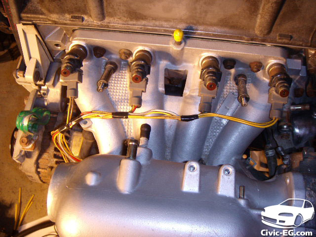
[img]http://www.6thgearadvertising.com/misc2 ... uck/72.jpg[/img]
Here's looking at the injectors from the opposite side.
BRN - RED - BLU - YEL
be sure to double check them with a meter
black88si wrote: I am having a hell of a time figuring out how to de-pin my injector plugs....
Anybody know if it is even possible?
.adam. wrote: to depin the injector plugs get some needle nose pliers and pull really really hard on the little white circle tab thing sticking out where the two wires come out.
eblucarbonem1 wrote: quick question tho, when doing the main harness are you guys just extending wires or are there certain resistances that need to be met? how hard is this exactly any quick tips? thanks
AnToNy wrote: Shortening or extending a wire does not change the resistance going through it.
so it will not make a difference
DC2 Mang wrote: but there will be a power drop of around .1 volts at the points where you connect and solder
that is why you avoid cutting the o2 sensor wires because their signal to the ecu is between .1 and .9 volts
eblucarbonem1 wrote: so if im running 770's and doing a tuck harness do i need to run the wires through a custom resistor box or what?
- pins.RedZone wrote: you can use a stock honda resitor box and the wires are already at the end of the harness on the driverside strut box..... its the dead plug with the yellow/black wires....4 wires go to the injectors. If you trace out the wires at the dead plug, one wire will go to each injector. there should also be a power wire at the dead plug that turns on with the key. If you tap into this power wire and connect it to the power wire ont he resistor box and connect the 4 wires from the injectors to the 4 wires on the resistor box you will be able to now use low impedance injectors.
this is all assuming you have a civic or integra with a d or b engine
ejwan wrote: finally found the company that does our oem honda pins
its Tyco Amp here is the link to our pin that we need Tyco Amp Pin (Note: Under Instruction Sheets: click on the first link its a PDF file)
Not sure if its P/N 316836 which is the female pin size S. (size M is 316838). this is the 040 series there is also the 070.
I don't know the P/N for the male plug yet (if someone know it would be helpful)
- distributor wiring..dave wrote: PM user tony1. I believe he has a bunch of the pins.
not so JDM Dan wrote: you shouldnt have to shorten the distributor wires, i ran mine under the manifold and it came out perfect
[img]http://i3.tinypic.com/262nkud.jpg[/img]
hayce wrote: hmm done things a little different,
The wires that come out from the distributor (like your pic there) I have lengthened so the plug is under the manifold (mine orginally were shorter than yours, I aws your pics & believe me I tried )
The problem lies with the other end of the loom. I want to have the 5 plugs from the motor stopping under the heater hoses. Then the cabin side wires that connect to them peaking out a hole ive made there. So with that in mind the length of the wires wrapped up in the black plastic + braid is too long.
not so JDM Dan wrote: oh i see, hmm so you want to be able to disconnect the engine harness from the engine bay under the heater hoses?
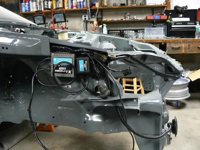
- tucking your hid kit.hayce wrote: Yeah. This is actually my 2nd go as the first time I did it I just ran the wires through the hole and then put the plugs on which, when I pulled the motor left the loom stranded/trapped in the firewall so I had to chop it (hole is not big enough to pass all the plugs through it)
Beau Gotti wrote: Question for people with HIDs: where is everyone hiding their sh*t
SkankyEJ7 wrote:[img]http://i17.photobucket.com/albums/b79/t ... C00676.jpg[/img]
and dont worry im pretty sure most all HID stuf is water RESISTANT! Noticce i did not say water proof, so im not liable if you try to submegre you hid's and cut them on
H8 O ATE wrote: thats where mine are, no problems so far, but i am using rubber stand offs, rubber washers, 2 reg bolts, 2 nylon bolts, and lock washers all around , might say its over kill, but i dont want my dis-continued HID's falling off on the freeway somewhere
as far as mounting, the Catz hid's have 4 bolt hole mounts on each corner, so all i did was drill & tap mounting holes on the frame rails
- special wire loom [sleeving]SHG_EasyE wrote: i ran my auxillary fan and hid wiring through the main harness to the fuse box and dash (for the fan switch)
[img]http://i29.photobucket.com/albums/c294/ ... 020798.jpg[/img]
[img]http://i29.photobucket.com/albums/c294/ ... 020691.jpg[/img]
KILLA_EK9 wrote: Where do u get this special wire loom thingy??? Anybody..
teamsoy1320 wrote: it is for computer wire...go to http://www.xoxide.com or http://www.newegg.com and you can get it there
wEaK Squad *ATL* wrote: 1/8", 1/4", 1/2", 3/4", and 1" are the loom sizes I’ve used
BolivianFuego wrote: Im a little late here, but to all good little boys who ask... Just call Clause...
http://www.parts-express.com/wizards/se ... N=53646450
eblucarbonem1 wrote: how much and what sizes of this stuff are you guys using to do main harnesses?
http://cableorganizer.com/f6-wrap-around/
- wiring/soldering basicsAmerican.Graffiti wrote: I went to SVC http://www.svc.com [thanks EF8Kid aka Cha$e aka ballaholic] and just used the black sleeving kit. I have a good amount left over, I just might do a once over on mine so I dont have it as a waste.
civicandy wrote: Since most of you guys are so good at wiring, I figured I would ask for tips. My current method is to use flux core solder and a soldering pen. I find that 2 hands is not really enough, since there are 2 wires, the solder and the soldering pen. Tips?
h22apwrdcivic wrote: get a clothes hanger and solder two aligator clips at two different points then use that to hold the wire tight while you solder. its what i use.
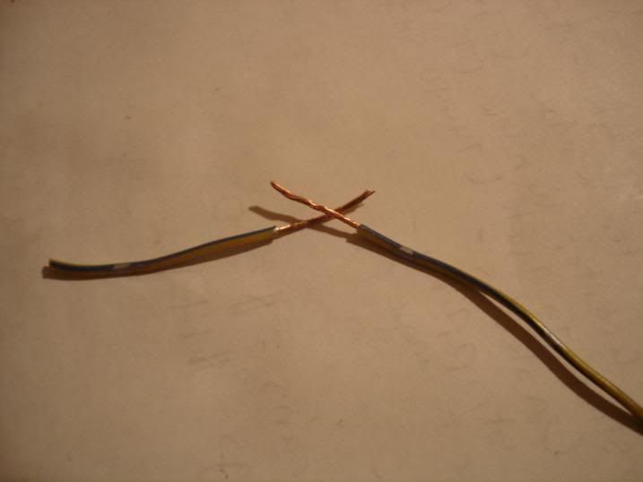
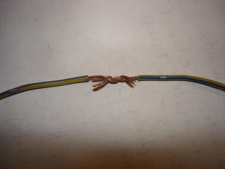
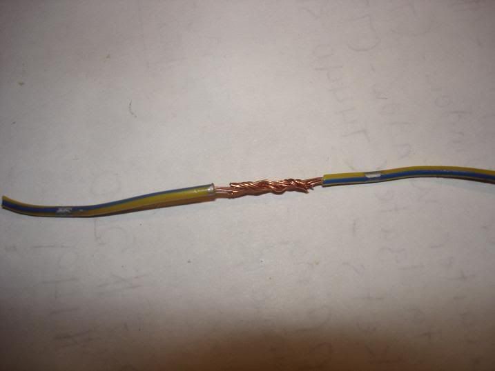
B18EG6 wrote: I just strip ~.25 - .5" of insulation from the wire, line the two wires up side by side, and twist them lengthwise around each other.
The end result is a soldered section no larger than the insulated wire, with no pointy pieces that could poke through the heat shrink
I doubt a picture is needed, but if you want one lemme know.
Also - hemostats work very well when holding wires while soldering
PatrickGSR94 wrote: I like to strip about 1" or a little more off each wire, make each wire into a hook shape, hook the wire ends together, then twist the ends and solder. That will make the absolute strongest solder joint, but you do end up with a slightly larger diameter than the original wire. If you have lots of wires with solders all next to each other then I guess that could be a problem.
EF8kid wrote: Follow these steps:
[img]http://img.photobucket.com/albums/v739/ ... -06034.jpg[/img]
[img]http://img.photobucket.com/albums/v739/ ... -06038.jpg[/img]
[img]http://img.photobucket.com/albums/v739/ ... -06039.jpg[/img]
then solder
wEaK Squad *ATL* wrote: ^ correct ^
but dont twist them too tightly because you want the solder to be able to penetrate each thread... solder does NOT sit on top in a bubble... when correctly done, it almost soaks into the wire and itll be very hard to pull apart again
PatrickGSR94 wrote: yep, and to do that, you need to heat up the wire so that the wire itself melts the solder. Don't melt the solder against the iron and let it drip onto the wires.
gabebauman wrote: PS: Don't forget to slide the heat shrink tube over one of the wires and set it back out of the way while soldering.
- ground wire on your valve coverh22apwrdcivic wrote: Oh yeah and you heat the wire and not the solder that way the heat sucks in the solder making a permanent connection.
B18C Turbo wrote: One thing I have noticed about all these sick bays are no one is using the ground for the valve cover? What are you guys doing, not using one at all or is it invisible?
Anyone got pics of where every ground should be? I know of the battery -, valve cover, and tranny.
- fuse box tuckEF8kid wrote: Put it on the back VC bolt
B18EG6 wrote: Would it be possible to extend the wires, and mount the underhood fusebox in the trunk? I thought about doing this... use 18ga wire to extend the smmaller wires, some 10ga and 8ga for the bigger ones.
Also I have about 20 ft of 0ga for the battery wires, and 4ga to run from the alternator to the fusebox
JDMorgan wrote: its VERY possible but thats like maybe ten 12 gauge wires, and an 8 gauge... thats alot of wire. not to mention the smaller gauge wires. the wire to the battery itself could be super short tho if you ran a wire right from the battery to the fuse block.
95jdmej1 wrote: as for a custom batt. tray do you mean just weld a smaller tray there ??????
What is the hard part about heater box and fuse box ? can i do it myself???
JDMorgan wrote: section the stock tray so that the bottem is the same size as your battery. if you relocated the fuse box under the dash i bet you could fit the whole battery in the space between the fwall and strut tower(instead of sticking out like oe battery does).
with the dash out the heater core, ac evap, and blower motor only have a few nuts and bolts holding them in. you could yank all of it out pretty quick, then just make a panel to weld or rivet in where the heater hose came thru the fwall. i am pretty sure on eg civics you can even put a din block off where the hvac controls were. i am not a fan of removing heat in general, but if you think it's worth it... go for it. there are actually a couple options if you did want to daily drive this car with no oem hvac shit... you can either run a universal heater box so you still have heat and defrost, these are electric so there is no hole in the fwall. the other option is heated windshield.
the fuse box relocation is pretty basic but takes a little work, mostly just unwrapping and rewrapping wires. if you are pretty good with wiring give it a shot.
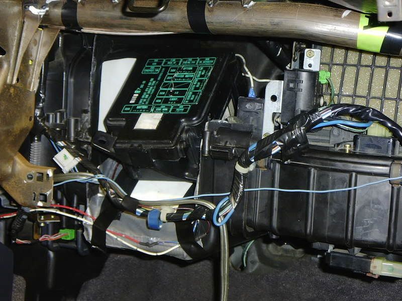
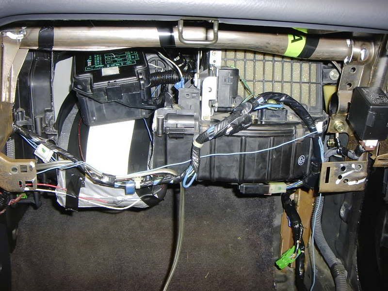
DarkBB4 wrote: just a ?, when relocating fuse box.. how do u get the oem honda plugs through teh firewall?
Madness wrote: Uhmm.... Definately not. Disconnect them from the box, and push them throught the firewall one at a time.
h22apwrdcivic wrote: yeah they all disconnect from the fuse box, there are about 5-6 plugs on the back of the fuse box, disconnect and pull them back through the firewall and then reconnect. that was the easiest part. if you figured that part is confusing you might want to cease all further projects.
American.Graffiti wrote:[img]http://img480.imageshack.us/img480/5096/1011325al9.jpg[/img]
Thats a test fit before I put the dash back in the car. Dont mind the cover, its fu_ked and I have a brand new one anyway.
JDMFantasy2k wrote: how bout this for a fusebox relocation
[img]http://img.photobucket.com/albums/v217/ ... s/0006.jpg[/img]
[img]http://img.photobucket.com/albums/v217/ ... s/0008.jpg[/img]
yeah that took a lot of creativity. Works good though, plus the glove box is still useable

- low brake fluid switchNHswaps13203 wrote: run no heat haha, wait dont do that thats why i sold that car.
[img]http://img108.imageshack.us/img108/961/h2b25uf9.jpg[/img]
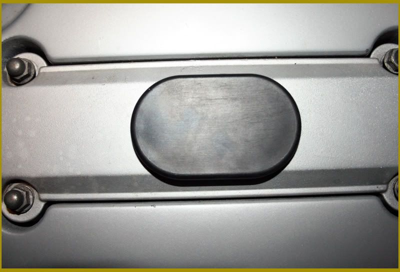
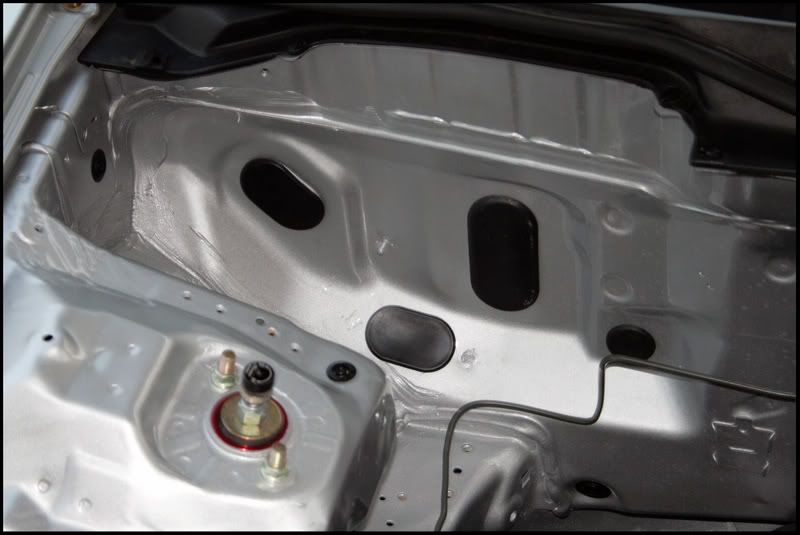
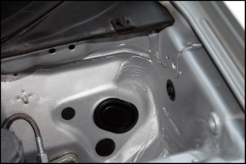
B18C Turbo wrote: Just wondering what to do about holes that im drilling to run wires thru. I need to cover the holes with a water tight seal, for example I drilled a hole in the vents in front of the windshield for the wiper wires to go under the dash rather thru the brake booster.
SO now i need to seal that hole up, and seal up the hole where the wires originally came thru to the engine bay, help.
JDMorgan wrote: brake fluid switch: remove the ground from the ground block and the signal pin from the connector right behind the firewall. then you can just take the switch off the cap and it looks way cleaner. if you dont notice your brake fluid low on your own maybe cars aren't your thing. ahaha.
wiper wiring: is a bitch. the best way to do it is cut a rectangle around the grommet hole already there, then another rectangle the same size on the firewall between the cabin and the cowl area so it isnt visible from the bay. then just but weld the pieces of metal in the opposite hole. then just run the wiring all inside your cabin right to the cowl and ur done.